
The aviation project
A hydrogen-electric aircraft, built to find the real problems.
An experimental aircraft based on a Zenith CH-750, used as a practical technology demonstrator for the complete propulsion and energy system.
- Registration
- HB-YSB
- Platform
- Zenith CH-750
- Role
- Technology demonstrator
- Energy
- Hydrogen fuel cell and battery
- Drive
- Electric
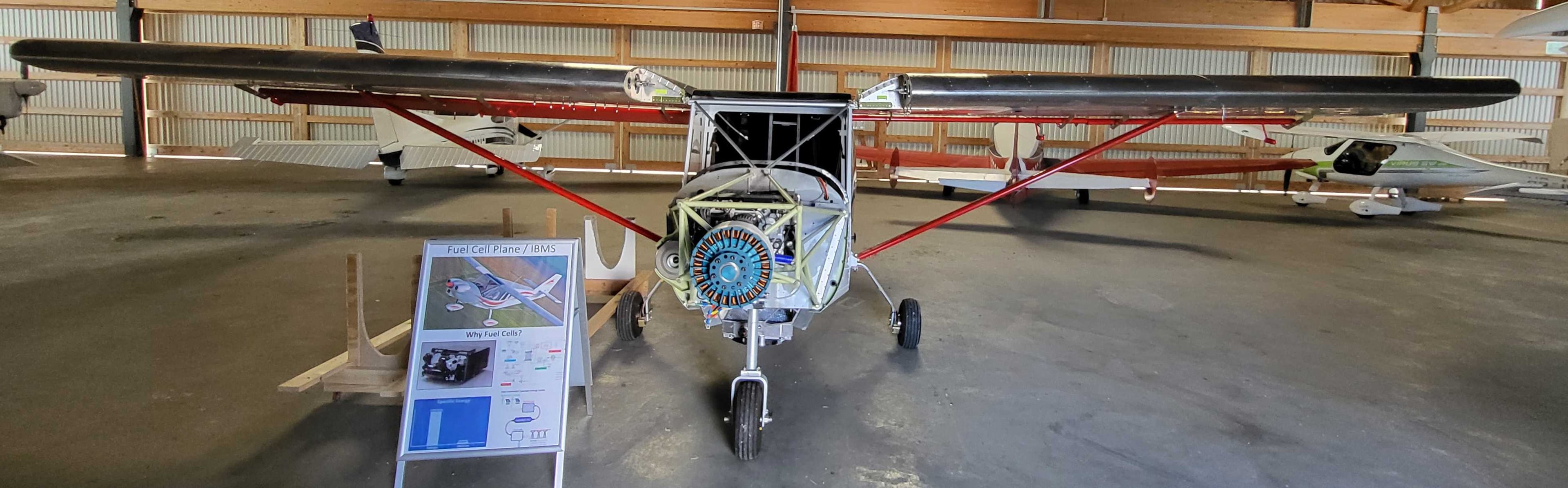
The intent
The aircraft is the test platform, not the goal.
The important part is not converting one small aircraft to hydrogen. The Zenith CH-750 is the first practical development and test platform for a broader approach.
It carries the complete system, from the hydrogen on board to the propeller, so that every interface is real: storage, fuel cell, battery, drive, cooling, power distribution, control and monitoring, all in one airframe and all expected to work together.
That makes it both a real aircraft project and a way of investigating how hydrogen-electric aviation can work as a complete, practical system.
The system
One chain, from tank to propeller.
Energy path
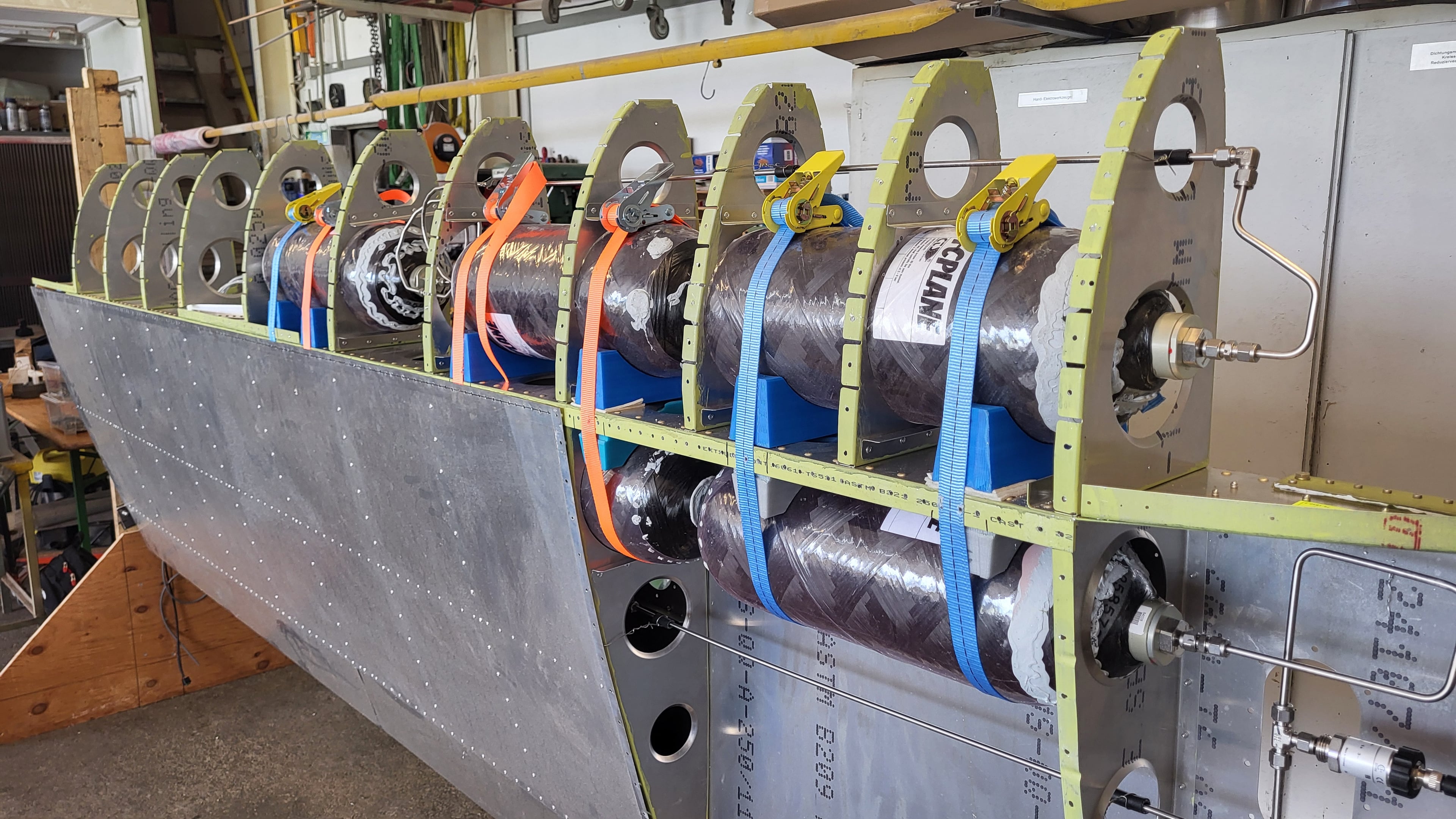
- 01Hydrogen storagePressure tanks integrated into the airframe.
- 02Fuel cellThe primary energy source in flight.
- 03Battery bufferCovers peak demand and the transients the fuel cell should not see.
- 04Power distributionRoutes, switches and protects power between sources and loads.
- 05Motor and controllerElectric drive to the propeller.
What holds it together
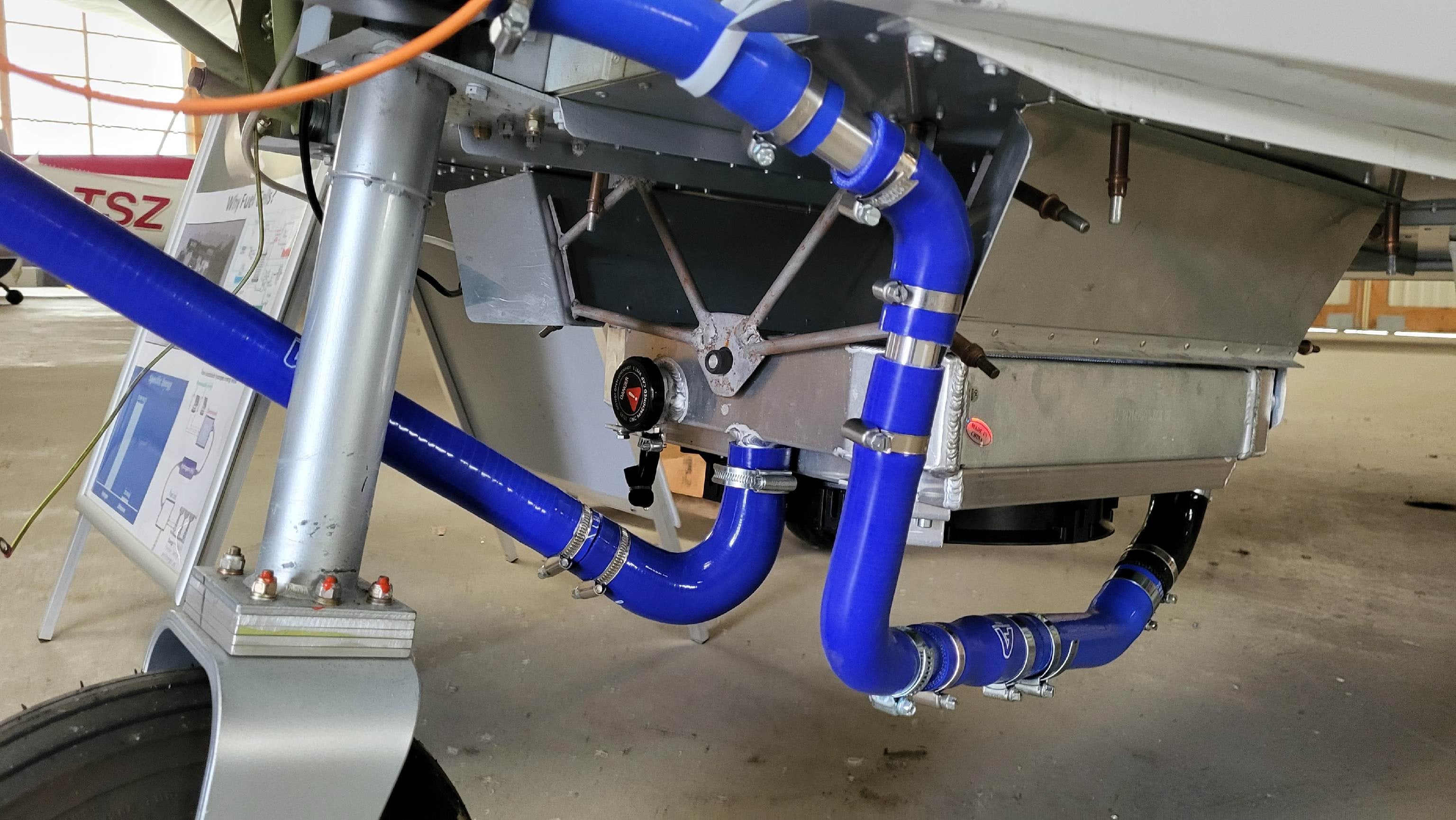
- CoolingRemoves heat from the fuel cell and the drive.
- Control electronicsSupervises the system and holds it inside its limits.
- CAN communicationOne network between every controller on board.
- System monitoringPressures, temperatures and states, recorded and alarmed.
Grassroots development approach
Start small, build it whole, let testing decide.
Only solutions that prove themselves in practice are scaled up.
- 01
Start at a manageable scale
A light aircraft, not a commercial one. Small enough to build, change and test quickly.
- 02
Use what is available
Commercially available technology, so effort goes into the system and not into reinventing components.
- 03
Integrate a complete system
Every part of the chain in one real aircraft, not a subsystem on a bench.
- 04
Test extensively
Find the actual technical and operational problems, not the ones predicted on paper.
- 05
Scale what proves itself
Only solutions that work in practice move on towards larger, commercially useful aircraft.
Workshop and hangar
Built by hand, in the workshop and the hangar.
Safety concept
Layered, so no single measure stands alone.
Each layer assumes the one outside it can fail.
- Marking and documentation
- Clear marking of the system on the aircraft, a description in the handbook, and a guide for the fire service.
- Safe refuelling
- Grounding before fuelling, monitoring of pressures and temperatures throughout, and a supply that is cut if anything departs from normal.
- Detection
- Hydrogen sensors where gas could collect, and pressure monitoring designed to recognise both a slow loss over time and a sudden drop.
- Isolation
- Valves that stay closed unless they are actively held open. On a fault the design interrupts the supply, alerts the cockpit, and allows the system to be shut down or switched to battery power.
- Controlled venting
- Pressure and temperature relief that releases the hydrogen quickly at defined points on the airframe if heat or pressure rises.
Beyond the aircraft
Hydrogen where the aircraft actually lands.
The longer-term concept includes hydrogen supply for smaller and remote airfields, where a fuel delivery cannot be taken for granted.
Organisations involved
The project does not stand alone.
- BAZLSwiss Federal Office of Civil AviationFormal agreement
- BRUSABRUSA HyPowerFormal agreement
- OSTEastern Switzerland University of Applied Sciences
- Zenair Deutschland
- Flugplatz SitterdorfSitterdorf airfield, Switzerland